Focal Reducers for Astronomy
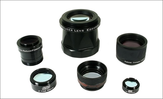
Figure 1 – Focal reducers of various designs and manufacturers. Image credit and copyright Agena AstroProducts.
- 1. Introduction
- 2. How Focal Reducers Work
- 2.1 Some Basic Definitions
- 2.2 Using a Focal Reducer at the Working Distance
- 2.3 Adjusting the Reduction Factor of a Focal Reducer
- 3.Types of Focal Reducers
- 3.1 Overview
- 3.2 Focal Reducers for Refractors
- 3.3 Focal Reducers for Compound Telescopes
- 3.4 Focal Reducers for Newtonians
- 3.5 Focal Reducers for Ritchey-Chretien and Field Flattened Scopes
- 3.6 Focal Reducers in 1.25" and 2" Barrel Formats
- 4. Practical Considerations of Focal Reducers
- 4.1 Field of View and Image Circle
- 4.2 Back Focus Requirements of Focal Reducers
- 4.3 In-Focus Travel
- 5. Summary
- 6. References
- Appendix
1. Introduction
Most amateur astronomers are familiar with a Barlow lens (or a focal extender), a negative or diverging lens that effectively increases the focal length and the focal ratio of a telescope's objective lens. A longer effective focal length leads to higher magnification with a given eyepiece for visual observers. It also leads to larger (although fainter) images of extended objects like the Moon or planets for astrophotographers or visual observers.
A focal reducer does just the opposite of a Barlow lens or focal extender. A reducer is a set of converging (or positive) lenses that cause the light from a telescope objective to converge at a steeper angle to the focal plane as if it were coming from an objective with a faster (lower) focal ratio and a shorter focal length. When placed in the focal plane in front of a camera or eyepiece, a focal reducer leads to a wider field of view and a brighter image of extended objects, which is important for reducing the exposure times when imaging faint extended objects like nebulae or galaxies. A wider field of view and a lower magnification is also useful, with some focal reducers and with some eyepieces, for visual observers with telescopes with long focal ratios.
In some cases, focal reducers also act as field flatteners by correcting for field curvature and coma of the objective lens.
This article explains the basics of how focal reducers work with an astronomy telescope. It covers the basic optics and design specifications of a focal reducer, and goes through some practical factors to consider when selecting and using a focal reducer.
2. How Focal Reducers Work
2.1 Some Basic Definitions
First, let's have a look at some key optical parameters are needed to understand focal reducers.
The design reduction factor of a focal reducer is the relative amount by which the effective focal length of the telescope is reduced when the focal reducer is used at its specified working distance or back focus. This factor is designated by a power that is less than 1, and it usually lies between 0.5x or 0.8x. For example, with a 0.8x focal reducer, a telescope with a focal length of 800mm will operate at 800 x 0.8 = 640mm when the reducer is placed at the working distance specified by the manufacturer.
The amount of reduction is simply the percentage by which a reducer shortens the effective focal length of a telescope and is calculated as (1 – Reduction Factor) x 100%. For example, a 0.8x reducer placed at the working distance provides a reduction of (1 – 0.8) x 100 = 20%. The Reduction Factor and the Amount of Reduction are inversely related. As one increases, the other decreases.
Each focal reducer has a fixed specification called the working distance or required back focus. It's usually specified in millimeters. This is the distance at which the reducer must be placed in front of the eyepiece or camera focal plane in order to operate at the design reduction factor. Most manufacturers provide this specification. It's usually specified from the base of the mounting threads on the reducer's housing, and this is the most practical way of providing this specification. Some manufacturers will specify the working distance from the middle of the rear lens surface, and this number must then be converted into a practical working distance number by subtracting the amount by which the rear lens surface is recessed in its housing.
Most focal reducers are designed to operate optimally at the working distance in the optical path to achieve their specified reduction factor, which is usually between 0.5x and 0.8x. If the reducer is placed elsewhere, at a position called the operating distance, the focal reduction factor will not be as advertised. More about this below.
The focal length of a focal reducer is usually measured from the rear lens surface of the reducer (and not the reducer's housing). However, manufacturers virtually never provide this specification. The working distance or required back focus, explained above, is usually specified and is far more important in practice.
Figure 2 shows the effective of a focal reducer on the light from a telescope objective. More details are found in the Appendix of this article.
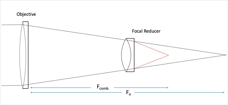
Figure 2 – A schematic of a focal reducer, which act to reduce the focal length and the focal ratio of a telescope objective. The combined focal ratio of objective and reducer Fcomb, is less than the focal ratio of the objective, Fo. Image credit and copyright Agena AstroProducts.
2.2 Using a Focal Reducer at the Working Distance
The easiest way to use a focal reducer is to make sure you place it at the specified working distance in front of your camera or eyepiece. If you do so, you will achieve the design reduction factor. Perhaps not exactly- there will be some uncertainty because of manufacturing tolerances and so forth, but it will be close. The equations and argument in the Appendix of this article shows the relationship between the working distance and the reduction factor.
For example, many focal reducers designed for f/7 or f/8 ED refractors such as those from Tele Vue, William Optics, Sky-Watcher, and Meade are designed to have a working distance (or back focus) of 55mm. That means the base of the mounting threads of the focal reducer needs to be 55mm from the camera sensor to achieve the design reduction factor, which is usually 0.8x or 0.85x. You may need spacers or a T-adapter to ensure the correcting working distance. If you place your camera at a different working distance, you will get a different reduction factor and perhaps unwanted distortion in the image. Focal reducers for these relatively fast ED refractors are generally for imaging only, not for visual observation.
As another example,GSO makes focal reducers for their line of Ritchey-Chretien imaging telescopes. These reducers have a back focus (or design working distance) of 80mm. When the camera sensor is placed at this distance, the reduction factor of these reducers is 0.75x.
2.3 Adjusting the Reduction Factor of a Focal Reducer
Many focal reducers are meant to be used within a few millimeters of the specified working distance to achieve the best possible image results. If used before or beyond the working distance, unwanted image distortion may result, especially when using cameras with larger sensors.
However, in principle, the reduction factor of a focal reducer can be varied by changing the distance from the back of the focal reducer to the camera or eyepiece. The equations in the Appendix show how this all works. You don't need to follow these equations to use a focal reducer, but they do show how the reduction factor changes with the placement of the reducer. The key points are as follows:
- A focal reducer will provide its design reduction factor only when it is placed at the exact working distance from the focal plane of the eyepiece or camera
- Reducing the operating distance, that is, moving a focal reducer closer to the eyepiece or camera increases its reduction factor, or conversely reduces the amount of focal reduction
- Increasing the operating distance, that is, moving a focal reducer away from the eyepiece or camera reduces its reduction factor, or conversely increases the amount of reduction.
So just remember that a smaller distance (from the camera or eyepiece) means a lower amount of reduction (and vice versa).
As a real-world example plot showing the above relationships, let's look at the 1.25" GSO focal reducer that provides a design reduction factor of 0.5x. The focal length and design working distance for this focal reducer were not available from the manufacturer. However, with appropriate spacers and a camera with a known back-focus, it is easy to determine the exact amount of focal reduction for a given setup (some imaging software packages will also let you derive this from images). We tested GSO's 1.25" 0.5x focal reducer at a variety of operating distances and calculated the field of view through a telescope to derive the actual reduction factor that is plotted below.

Fig 3 – The measured reduction factor of a GSO 1.25" 0.5x focal reducer as a function of operating distance. The working distance (or required back focus) of this component is approximately 51.5mm. Image credit and copyright Agena AstroProducts.
Even though the manufacturer did not specify the working distance or focal length of this reducer, it is easy to see from this plot that this item provides its stated reduction of 0.5x when it is placed at a working distance of 51.5mm between the base of the threads on the mount and the focal plane of the eyepiece or camera. Using these numbers in equation 4 in the Appendix, below, we can easily calculate that the focal length of this unit is approximately103mm (it will be 103mm plus the small amount by which the rear lens surface of the reducer is recessed beneath the reducer housing).
In practice, it's important to remember that you will rarely operate at the exact working distance and at the exact reduction factor that is specified. The designed reduction factor (0.5x in the case of the GSO reducer example above) should be considered a rule of thumb or approximate value in most cases, rather than a very precise number.
3.Types of Focal Reducers
3.1 Overview
While most Barlow lenses and focal extenders work with most kinds of telescopes available to amateur astronomers, focal reducers are designed to work in a narrow range of focal ratios of a telescope objective. That's partly because focal reducers correct for field curvature, which itself depends on the focal ratio and other optical design factors of the telescope. One focal reducer will not achieve optimum results with all types of telescopes, so there is no “universal' focal reducer.
Focal reducers (and focal reducer/field flatteners combos) are usually used with two types of telescopes, refractors and compound telescopes such as Schmidt-Cassegrain or Ritchey-Chretien.
3.2 Focal Reducers for Refractors
Focal reducers for refractors with focal ratio of f/7 to f/9, roughly, have a design reduction factor of about 0.75x to 0.8x and produce a flat field by correcting for the curvature of the objective lens. Most refractor manufacturers such as William Optics, Tele Vue Optics, Explore Scientific, Sky-Watcher, William Optics, and Stellarvue make their own focal reducers optimized for use with their telescopes. There are also third-party vendors such as Hotech. In most cases, the easiest option is to choose the focal reducer made specifically for your telescope. However, some focal reducers can be used on other models of telescopes, but this is not always possible.

Figure 4 – An 85mm f/7 refractor with a 0.7x focal reducer inserted into the focuser. The reducer has a working distance (back focus) of 55mm, which is taken up by a 10mm T-ring inserted into the camera and a 46mm distance from the camera flange to the sensor, close to suggested working distance. Image credit and copyright Agena AstroProducts.
Focal reducers for refractors are easy to use. They usually have a 2" barrel that slides into the telescope focuser. The telescope side of the barrel is often threaded with an M48 x 0.75 thread for standard 2" astronomy filters. The camera side of the focal reducer is threaded for a T-adapter with wide M48 threads, or in some cases, with smaller M42 threads.
Dedicated focal reducers for refractors are intended primarily for imaging, not visual observation.
Some faster refractors with a focal ratio of f/6, for example, only require field flatteners and not focal reducers. Some refractors such the TeleVue Nagler-Petzval (NP), the Takahashi "FSQ", and the William Optics Redcat/WhiteCat 51 have inherently flat fields because of internal optical elements. Depending on the design of the telescope, they may require separate focal reducers if they require focal reducers at all.
3.3 Focal Reducers for Compound Telescopes
Because of their distinct optical design, slower Schmidt-Cassegrain telescopes (SCT) with focal ratios of f/10 require a different design of focal reducer compared to refractors. Again, these focal reducers are often provided by the telescope manufacturer.
The most commonly available focal reducers for SCTs are the f/6.3 reducers from Celestron and a similar f/6.3 focal reducer from Meade. Some third-party vendors also make reducers for SCT scopes. These 0.63x focal reducers were originally designed to optimize for an image circle to match 36mm x 24mm film or its digital equivalent for astrophotography. These reducers can also be used for visual observing with SCT scopes with eyepieces with a field stop as large as 24-27mm. For both imaging and visual observing, these reducers also improve image sharpness at the edge of the field by correcting for coma and field curvature.
Meade once made an f/3.3 focal reducer for SCT scopes. It was used strictly for imaging, not visual observing. This part is no longer in production, but it is sometimes available used and may be used with cameras with smaller sensors.
The naming convention of SCT focal reducers is a little confusing. An f/6.3 reducer is designed to reduce the focal ratio of an f/10 SCT to f/6.3. So it provides a 0.63x design reduction factor when used with an f/10 SCT at the specified working distance. The working distance (backfocus) of the Celestron f/6.3 reducer is specified to be 105mm from the base of the male SCT thread on the camera side.
Unlike SCT telescopes, Ritchey-Chretien telescopes and Celestron Edge HD or Meade ACF scopes have internal optics that provide an inherently flat field, so these telescopes require a special focal reducer than does not provide additional correction for field curvature. You cannot, for example, use a 0.63x focal reducer intended for a standard Celestron or Meade SCT and use it on a Celestron Edge HD or a Meade ACF.
Focal reducers for SCT, RC, and field-flattened Edge HD or ACF telescopes thread onto the back of the telescope tube with 2"-24 or 3"-28 SCT threads. The visual back must be removed first. If the focal reducer is to be used for visual observation, the visual back is threaded onto the eyepiece side of the reducer, and then a star diagonal and eyepiece are installed as usual. For imaging, a T-adapter is threaded to the camera side of the focal reducer, which in turns connects to the camera with the appropriate hardware.
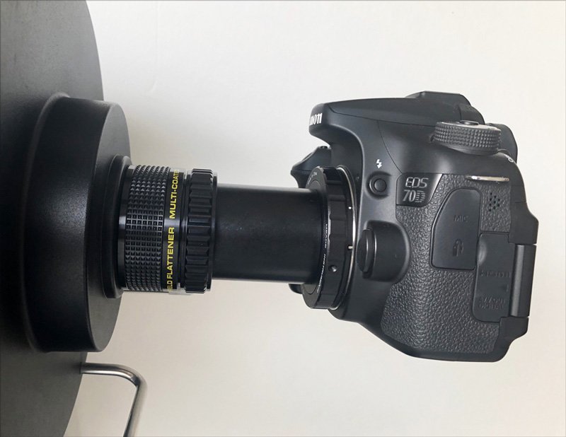
Figure 5 - A Schmidt-Cassegrain telescope with a focal reducer/field flattener threaded to the back of the optical tube in place of the visual back. Image credit and copyright Agena AstroProducts.
3.4 Focal Reducers for Newtonians
Because most modern Newtonians already have relatively fast focal ratios, these telescopes do not usually use focal reducers. Using one on such a scope would make demands on the eyepiece design and increase the exit pupil to an extent that focal reduction on fast Newts is not practical. Also, the focusers of most Newtonians do not have enough in-travel to accommodate a focal reducer.
3.5 Focal Reducers for Ritchey-Chretien and Field Flattened Scopes
Advanced designs for Schmidt-Cassegrain scopes such as the Meade ACF or Celestron Edge HD have optical elements in the tube to correct for coma and field flatness. As a consequence, the standard f/6.3 and f/3.3 focal reducers for SCT scopes do not work. Specially-designed focal reducers are available for use with these telescopes. Celestron makes a series of focal reducers for the Edge HD line that are matched to the 8", 9.25", 11", and 14" apertures of these scopes. Meade does not make an equivalent line of focal reducers for the ACF scopes, although some models of Meade ACF are already at f/8, faster than the f/10 ratio of Celestron Edge HD scopes.
Many Ritchey-Chretien telescopes available today are made by GSO. They provide 0.75x focal reducers for these telescopes that takes an f/8 instrument down to f/6. These RC reducers cannot be used with other types of telescopes.
3.6 Focal Reducers in 1.25" and 2" Barrel Formats
For imagers using longer focal-length refractors and SCTs, especially when using smaller sensors that place less demand on the focal reducer, there are economical alternatives for focal reducers from manufacturers such as GSO, Agena, and Antares. They are commonly available in 1.25" and 2" threaded cells that conveniently thread into the nosepiece of a compatible camera or the barrel of an eyepiece. Some are available in 1.25" barrel format but with C threads.
The nominal design reduction factor of these reducers is typically 0.5x. The working distance of the GSO 0.5x focal reducer with 1.25" barrel and the GSO 0.5x focal reducer with 2" barrel is about 51mm to 53mm, approximately, from the middle of the metal cell that holds the lens. Figure 6 shows a 1.25" focal reducer from GSO configured with a ZWO ASI224MC camera. In this configuration, the 29.5mm camera nosepiece and a 6mm extension ring positions the reducer at a working distance of 53.5mm from the camera sensor, which is located 12.5mm inside the front edge of the camera. The resultant reduction factor was measured to be 0.46x.
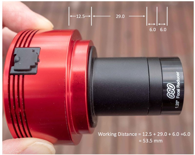
Figure 6 – A ZWO ASI224MC camera configured with a GSO 0.5x 1.25" focal reducer at its specified working distance of 53.5mm. Image credit and copyright Agena AstroProducts.
As mentioned in Section 2.3, the reduction factor for these focal reducers can be varied by adding spacers to move the reducer further from the camera sensor or eyepiece. Since the focal plane of an eyepiece is rarely precisely known(except for some brands such as Baader Planetarium and Tele Vue), and because the nosepiece of an eyepiece is of a fixed length, the actual reduction factor will be close to, but not exactly at, its designed reduction factor.
Can these economical focal reducers from GSO and other vendors result in good images? In many cases, the answer is yes, especially for electronically-assisted astronomy (EAA). This is especially true when these reducers are used with cameras with smaller sensors with a dimension of about 1/4 to 1/3 the diameter of the reducer, and with telescopes with a focal ratio of f/7 or larger. Better images are also obtained when using these focal reducers at a reduction factor of 0.5x – 0.8x, approximately. More aggressive reduction, or using these reducers with larger sensors, will result in aberrations and distortions near the edge of the image. Figure 7 shows an example of an image of the Dumbbell Nebula taken with a 1.25" GSO focal reducer at a reduction factor of 0.63x with an 85mm f/7 refractor and a QHY5III-290M camera with a sensor with a 6.4mm diagonal. Some coma is visible in the corners, but the image is quite good for EAA applications.

Figure 7 – An image of the Dumbbell Nebula (M27) with a GSO 1.25" focal reducer at a working distance that yielded a reduction factor of 0.63x with an 85mm refractor with a nominal focal length of 600mm. The camera used was a QHY5III-290M with 1920x1080 resolution and a sensor with a 6.4mm diagonal. Image dimensions are 50' x 28'. Image credit and copyright Agena AstroProducts.
4. Practical Considerations of Focal Reducers
4.1 Field of View and Image Circle
For imagers, the main purpose of a focal reducer is to increase the brightness of the image at the focal plane. But while the image gets brighter, the size of the image circle gets proportionately smaller. For example, an 8" SCT without a focal reducer has an illuminated field of 38mm at 50% fall-off. Add a 0.63x reducer, and the brightness of extended objects increases by (1/0.63)2 = 2.5. But the diameter of the image circle decreases by a factor of 0.63 to about 24mm. Such an image circle is still large enough to encompass the relatively large sensor of many deep-sky astronomy cameras. If a stronger level of focal reduction is used, say 0.5x, then the image circle may be too small to fill the sensor of larger cameras.
How about for visual observers? Using this same example of an 8" SCT and a 0.63x reducer, a visual observer can also enjoy brighter images and a wider field of view. But the smaller image circle means there is a limit to the field stop of an eyepiece that can achieve an unvignetted image. An image of about 24mm across, approximately, allows an observer to use a 1.25" eyepiece with a maximal field stop. That includes, for example, a 1.25" eyepiece with an apparent field of view of 68° and a focal length of 24mm (eg. a Tele Vue Panoptic), or a Plossl eyepiece with an apparent field of view of 50° and a focal length of 32mm. With this telescope and this focal reducer, it does not help to move to a 2" eyepiece and a 2" diagonal as the visual view will be akin to looking through a porthole within the larger apparent field of view of the eyepiece.
Another factor to consider: focal reducers also increase the angle at which light approaches the focal plane. This may be a problem if the focuser tube or the diagonal (for visual observing) is too narrow to accept light at this larger angle. As a result, the smaller tube may cut into the light cone and effectively reduce the working aperture of the telescope.
4.2 Back Focus Requirements of Focal Reducers
Many focal reducers for refractors have a working distance (or back focus distance) of 55mm. This standard distance is a consequence of the design of DSLR cameras for which the distance of the sensor to the outer edge of the flanges is about 45 mm, while the T-ring that attaches to the flange for astrophotography is about 10mm thick. On the camera side, the focal reducer has male M42x0.75 or M48x0.75 threads that attach directly to the T-ring (with an M42-M48 adapter if necessary). If you are using a camera that has a back focus of less than 55mm, additional spacer rings will be required between the reducer and the camera. It's important to match the back focus to within a millimeter or two to get an optimal image, especially with cameras with larger sensors.
Focal reducers for many SCTs and their flat-field equivalents usually have a back-focus distance of 105mm. In this case, an additional T-adapter (with an optical length of 50mm) is needed to get the spacing correct for a DSLR or other camera with a 55mm back focus. Meade and Celestron both sell such SCT-T adapters with the correct optical length.
For Ritchey-Chretien telescopes such as those manufactured by GSO, there are also dedicated focal reducers with a reduction factor of 0.7x to 0.8x. GSO, for example, has a 0.75x reducer for RC scopes with a back focus of 80mm, which is usually enough room for a wide range of astronomy cameras and accessories and spacers as needed.
4.3 In-Focus Travel
Focal reducers also move the effective focal plane of the objective inward, that is, towards the objective (see Figure 1). The more focal reduction, the further inward the focal plane will be. This means that there must be sufficient travel on the telescope focuser to make up for this. Stock focusers in an SCT move the mirror of the scope to change the position of the focal plane, and they have sufficient travel to accommodate a focal reducer. Refractors, or SCTs with external focusers, may not have sufficient in-travel to reach focus in some configurations. Newtonian reflectors will seldom be able to accommodate the in-focus travel demanded by focal reducers.
5. Summary
Focal reducers are essential optical accessories for astrophotography, electronically-assisted astronomy (EAA), and in some cases, for visual observation with long focal ratio telescopes. When placed in the focal plane in front of a camera or eyepiece, a focal reducer leads to a wider field of view and a brighter image of extended objects, which is important for reducing the exposure times when imaging faint extended objects like nebulae or galaxies. In some cases, focal reducers also act as field flatteners by correcting for field curvature and coma of the objective lens. This article explained the basics of how focal reducers work with various kinds of telescopes and how their working distance affects their reduction factor, and it provided sufficient detail to help amateur astronomer choose and use the right focal reducer for a particular application.
6. References
Telescope Optics, Rutten and van Venrooij, Chapter 15, Willman-Bell (1988).
APPENDIX
As mentioned in Section 2 of this guide, the reduction factor of a focal reducer depends on its position in the optical path relative to the eyepiece or camera. Most reducers have a design reduction factor, MRD, that assumes the reducer is placed at a specific working distance, D, from the back surface of the focal reducer itself. If the reducer is placed closer to the eyepiece or camera than the distance D, the reduction factor decreases. If it's positioned further from the eyepiece or camera and closer to the telescope objective, the reduction factor increases. This appendix summarizes how this works based on simple equations from the book Telescope Optics by Rutten and van Venrooij.
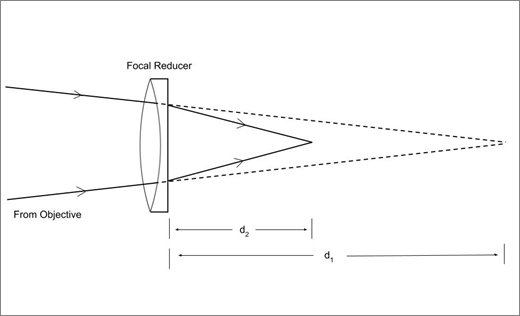
Figure A1 – The rays of light from a telescope objective (not shown) passing through a focal reducer placed at a distance d1 inside the focal plane of the objective. Light comes to a focus at a distance d2 from the back of the focal reducer.
Figure 1 shows the relationship between the focal reduction factor MR and the position of the reducer in the optical path. In these equations:
- d1 is the distance from the back of the focal reducer lens surface to the original focal plane of the telescope objective
- d2 is the distance from the back of the focal reducer lens surface to the new focal plane of the objective with the focal reducer where the camera or eyepiece is placed
- Fo is the focal length of the telescope
- Fcomb is the focal length of the objective with the focal reducer, which is less than Fo
- MR is the reduction factor of the focal reducer
- FR is the focal length of the focal reducer.
The combined focal length of the objective and focal reducer is given by Equation 1:
For example, when d1=0, that is, the focal reducer is at the focal plane of the objective, Fcomb=Fo, so the focal reducer has no effect. And when d1 = FR, that is, when the focal reducer is placed at a distance from the focal plane of the objective that's equal to the reducer's focal length, the focal length of the combined optical system is ½ Fo, so it acts as a 0.5x reducer. In this case, d2 = FR/2, which means the back of the focal reducer is located at a distance FR/2 from the camera or eyepiece.
The distances d1 and d2 can also be expressed in terms of the focal length of the focal reducer FR with the lens equation:
Using Equation 2, Equation 1 can also be expressed in terms of d2:
Fcomb = Fo(1 - d2/FR)Eq. 3
The focal reduction factor of the focal reducer depends on its focal length and its distance from the focal plane of the objective as shown by Equation 4:
Again, for example, when the focal reducer is placed at the original focal plane of the objective, d1=0 and MR=1, which means there is no focal reduction. Or, when the distance of the focal reducer to the focal plane of the objective d1 equals the focal length of the focal reducer FR, the reduction factor MR = 0.5x.
The distance d2, which measures the position of the new focal plane of the objective from the back of the focal reducer is given by Equation 5:
In these equations, d1, d2, and MR are all variables that depend on each other through Equations 2 and 4.
The reduction factor MR can also be written in terms of d2 as:
When the focal reducer is placed at the working distance, D, that is when d2=D, then the reduction factor MR is equal to the design reduction factor MRD:
Equations (6) and (7) imply these important considerations:
- To achieve the design reduction factor MRD, the focal reducer must be placed at the specific working distance D. If it placed elsewhere, a different reduction factor will result.
- Reducing the operating distance d2, ie., moving a focal reducer closer to the eyepiece or camera increases its reduction factor, or conversely reduces the amount of reduction
- Increasing the operating distance d2, i.e., moving a focal reducer away from the eyepiece or camera reduces its reduction factor, or conversely increases the amount of reduction
Most manufacturers do not publish the focal length of their focal reducers, so it is not usually possible to calculate the working distance and design reduction factor. They only publish the value of D, the working distance (sometimes called the back focus distance) and the design reduction factor MRD. For example, the focal reducer for an 8-inch Celestron EdgeHD telescope has a design reduction factor of 0.7x and a specified working distance (or back focus) of 105mm. (Note: Using the simple equations above, the focal length of this reducer can be estimated to be about 350mm).
Many reducers, such as the Celestron HD focal reducer mentioned above, and many focal reducers for apochromatic refractors, are meant to be used within a few millimeters (or less) of the specified working distance to achieve the best possible image results. If used before or beyond the working distance, unwanted image distortion may result.
However, some focal reducers can be used over a wider range of working distances, especially those with simpler optical design, and especially when used with cameras with smaller sensors. Equation (4) shows the relationship between the distance d2 and the reduction factor MR. Since the focal length of the reducer, FR, is fixed, as d2 increases then MR decreases.