A Primer on Back Focus in Astronomy
Discuss this article in the AstronomyConnect.com forums
- 1. Overview
- 2. Back Focus of Telescopes and Guide Scopes
- 3. Back Focus of Optical Components for Astrophotography
- 3.1 Required Back Focus of Field Flatteners, Focal Reducers, and Coma Correctors
- 3.2 Working Distance of Focal Reducers
- 3.3 The Back Focus of an Astronomy Camera and Flange Focal Distance
- 4. Understanding Optical Path Length
- 5. Additional Tips
- 6. Examples
- 6.1 William Optics 50mm f/4 ‘RotoLock’ Guidescope
- 6.2 Small Petzval Refractor, DSLR, and a NO Focal Reducer
- 6.3 Small Petzval Refractor, DSLR, and a Focal Reducer
- 6.4 Small Refractor, Astronomy Camera, Focal Reducer, and Filter
- 6.5 Schmidt-Cassegrain Telescopes and f/6.3 Focal Reducer
- 6.6 Celestron RASA Telescope
- 7. Summary
1. Overview
Back focus – most amateur astronomers come across this topic eventually, and many are confused by what it means and in which circumstances. This article explains the back focus of telescopes and optical accessories like field flatteners and focal reducers, and why back focus is important for visual observers and especially for astrophotographers. Here you learn how to arrange your optics to meet back focus requirements, and you get to see some that illustrate many common examples of back focus in astronomy.
2. Back Focus of Telescopes and Guide Scopes
2.1 Back Focus Specification of Telescopes
Confusion about back focus often arises because it refers to two different ideas: the available back focus of a telescope, and the required or recommended back focus of corrective optical accessories like focal reducers, field flatteners, and coma correctors.
First, let’s look at the back focus of a telescope and guide scopes.
The back focus of a telescope is defined as the distance between the focal plane of a telescope’s objective lens or mirror and a reference point on the focuser of a telescope, usually the edge of the focuser drawtube when it’s fully racked in (see Figure 1). The back focus of a telescope is simply the maximum space you have to insert accessories such as diagonals, binoviewers, cameras, filters wheels, and other accessories and still achieve focus. It’s a purely mechanical parameter that’s defined by the focal length of the telescope and the physical length of the optical tube and focuser.

While the back focus of a telescope is an important concept, most manufacturers of refractors and Newtonians do not publish this specification. But most ‘general-purpose’ refractors are designed to have a sufficiently long back focus to accommodate star diagonals for visual observation. Refractors intended for imaging only (called astrographs) tend to have a smaller back focus because no diagonal is required, only a camera and a few accessories. Newtonian reflectors have a more limited back focus compared to refractors and catadioptric scopes.
For refractors and Newtonians, some of the available back focus gets used by the diagonal or eyepiece or other accessories. To account for the rest, you simply need to rack out (extend) the focuser or add extension tubes to reach focus. As long as you can reach the focal plane, you need not worry about additional adapters, spacers, extension tubes, or about the telescope back focus specification itself.
However, if you “use up” all the back-focus of a telescope by adding components that are too long, you won’t be able to reach focus because you can’t rack in the focuser any further towards the telescope. This is an especially common limitation with Newtonians. It’s also a problem when using binoviewers because light travels a much longer path than in a diagonal.
As an example of a back focus specification of a refractor, the Askar FRA400 76mm refractor has a relatively generous back focus of 140mm. Some Newtonians, by contrast, have a back focus that’s too small to even accommodate the much smaller distance of 55mm taken up by a T-ring and DSLR camera.
A solution to insufficient back focus of a telescope involves shortening the optical tube of a refractor, or altering the mechanics of a Newtonian to move the mirror closer to the focuser, which may require a larger diagonal mirror to avoid light loss. Needless to say, these are not recommended solutions for most users! Another option for a Newtonian is to replace the focuser with a shorter one.
With Schmidt-Cassegrain telescopes (SCTs), back focus works a little differently. The back focus specification for SCTs is simply the location of the focal plane when the telescope’s focuser is at a position at which the scope operates at its design focal ratio (usually f/10 or, less commonly, f/8). It’s typically close to about 5 inches or 127mm from the rear SCT thread. But SCTs are more forgiving than refractors or Newts. In an SCT, turning the focuser moves the primary mirror, which changes the focal ratio of the telescope changes slightly. This slight change in focal ratio is usually not noticeable in most situations. But in moving the mirror, the telescope delivers a huge range of focus travel which enables focus with optical components like diagonals or binoviewers.
If you want to get an estimate of the back focus of your telescope, you can use a simple technique. Aim your telescope at a well-lit moon after dark, remove the eyepiece or camera from the focuser, and rack the focuser all the way in. Take a white card or piece of paper and move it away from your focuser until you see the moon focused on the card. Measure the distance from the card to the edge of your focuser. That’s your approximate back focus.
Or you can use an extension tube with a small piece of translucent paper taped to the far end of the tube. Insert the tube into the telescope’s focuser and rack the focuser all the way in. Aim the telescope at the moon and move the focuser out until the moon’s image comes to focus on the paper. The back focus of the telescope is equal to the length of the extension tube (not including the section of the tube that was inserted into the focuser) plus the distance by which the focuser was racked out.
2.2 Back Focus Specification of Guidescopes
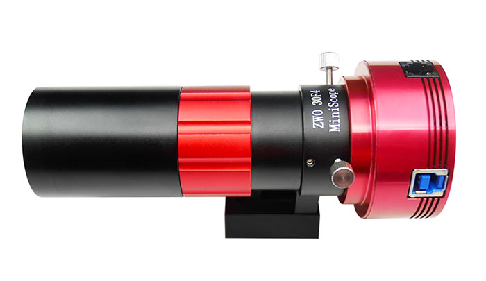
Guide scopes are a simple form of telescope, of course, so they also have a back focus specification. But guide scopes are intended for use with just one accessory: a small guide camera. So these little scopes tend to have a small back focus specification. For example, the William Optics 50mm f/4 guidescopes with RotoLock have a back focus of just 6.2mm. That means it can only come to focus with the small ‘mini guide cameras’ from ZWO, for example, the ZWO ASI290MM-Mini. Other guidescopes such as the William Optics UniGuide 30mm guidescopes or ZWO mini guidescopes (see Figure 2) have a more generous back focus of around 20mm that can accommodate a wider range of guide cameras with larger round bodies (such as the ZWO ASI290MM, for example).
3 Back Focus of Optical Components for Astrophotography
Now for a different kind of back focus, one that applies mostly to components used in imaging applications. This type of back focus is a little more challenging to grasp, and it’s often the bane of new astrophotographers. But it all relates to making sure that the optical accessories you use – focal reducers, field flatteners, and coma correctors – are positioned in the optical path at a location where they work as their designers intended. When you work with this back focus specification, you get a well-focused image across the designed image circle (and hence the sensor, as long as the image circle can accommodate the sensor), a uniformly illuminated sensor, and maximum correction of aberrations such as coma or field curvature.
This type of back focus is also completely unrelated to the available back focus of a telescope.
3.1 Required Back Focus of Field Flatteners, Focal Reducers, and Coma Correctors
The back focus of a field flattener or coma corrector is more accurately called the required back focus. It’s the distance from the base of the camera-facing (usually male) threads on the cell of the corrective element to the position at which the image plane of the camera must lie to get the best possible image (see Figure 3). Male threads are not included in the measurement of back focus because they are usually inserted into a female threaded element on the camera, either a T-ring or an adapter ring.

Figure 3 – An illustration of the back focus of a corrective optical element such as a field flattener or coma corrector.
The most common required back focus specification for these corrective optical components is 55mm, a quantity that’s based on the dimensions of SLR and DSLR cameras, as explained below. For many corrective components, the dimensions of the housing of the corrective optics makes achieving this back focus requirement easy; in other cases, spacer rings or even thread converters may be required.
The optical design of these components results in a rather small tolerance, typically 1 or 2mm in either direction. Image quality begins to deteriorate as you deviate from this required tolerance. (Some, like the GSO coma corrector, have a larger +/-5mm range). By conforming to the back focus tolerance of these optical components, you ensure:
- Sharpest image across the field of view (a flat field)
- Minimal optical aberrations
- An optimized and even illumination across the sensor
If the camera sensor isn’t placed at the required back focus, the images on the sensor become elongated and misshapen, especially off axis and especially with larger-sensor cameras. This is especially true when using fast telescopes since the focal plane is quite shallow.
If you see elongated stars off-axis in your images when using a corrective element, then you may need to adjust the position of the camera with spacer rings. If the stars appear to blur in short arcs around the center of the image, then the camera is too far from the corrective element. If off-axis stars appear to radiate away from the center, then the camera is too close.
On the other hand, with small-sensor planetary cameras, the position of the camera is far more tolerant to the back focus specification since the image on the camera sensor is much closer to the optical axis of the system.
3.2 Working Distance of Focal Reducers
Focal reducers, which are optical components used to increase the photographic speed of a telescope, usually have a specified working distance rather than a sacrosanct back focus specification. This distance governs where the eyepiece focal plane or camera sensor must be positioned to get the specified focal reduction (such as 0.8x or 0.63x, for example). Unlike the required back focus specification of correctors and flatteners, the true working distance can vary slightly more from the specified working distance. This will change the reduction factor somewhat. There is a limit, however: you don’t want to deviate too much as image quality will begin to suffer. See Agena’s focal reducer guide for more about this. Many focal reducers, especially for refractors, also incorporate field flattening elements, so they can be more sensitive to back focus.
One thing to keep in mind: once a reducer or corrective element is attached to the telescope, the available back focus of the telescope is no longer relevant. We now have only to consider the back focus or working distance of the element itself to make sure we can get to focus on the camera sensor. If the back focus of the component is 55mm, then the camera sensor must be placed 55mm away from the back of the cell of the corrector.
Insertion of field flatteners, coma correctors, or focal reducers changes the focal plane position of the telescope and will generally require a focus change, regardless of back focus specification. In some cases, the scope’s focuser may not be able to accommodate this change.

Figure 4 – In this cooled ZWO camera, the sensor is recessed 6.5mm from the top of the camera body and 17.5 mm from the top of the T2 ring when it’s attached to the telescope.
3.3 The Back Focus of an Astronomy Camera and Flange Focal Distance
Astronomy cameras don’t have a back-focus requirement by themselves. However, some manufacturers do specify a camera back focus distance, and many comments on astronomy forums refer to the back focus of a camera. They are referring to the distance, or path length, from the sensor of the camera to the top surface of the camera or to another reference point (for example, the top surface of a T2 ring mounted to the camera).
For example, with the ZWO ASI294MC-Pro camera, the sensor is 6.5mm from the top surface of the camera. When the included 11mm-long T2 adapter ring is threaded to the camera, the sensor is now 17.5mm from the top of the ring, so the “back focus” is 17.5mm (see Figure 4). Again, it is important to emphasize that this back focus is unrelated to the back focus of telescopes (Section 2) or corrective optics (Section 3.1).
For example, if you wished to use this ASI294MC-Pro camera with its 11mm T2 ring with a field flattener or focal reducer that has a specified back focus of 55mm, you would need to add another 37.5mm of space between the camera and flattener by using spacer rings. With this camera, for example, ZWO includes a 21mm and a 16.5mm T2 ring that can be combined and attached to the camera for this purpose (see Figure 5).

Figure 5 – A Tele Vue TR-2008 focal reducer with a 55mm back focus specification. At left, the reducer is used with a DSLR and T-ring with a combined 55mm path length. At right, a ZWO cooled camera with a sensor recessed by 17.5mm from the camera T2 ring is spaced from the reducer by a 16.5mm and 21mm T2 spacer ring for a working distance of 55mm.
DSLR and mirrorless cameras have a similar specification called flange focal distance (FFD). (We wish astronomy camera manufactures would have conformed with this same terminology)! The FFD is the distance from the cameras focal plane (where the sensor is located) and the front circular metal flange where the camera lens goes (Figure 6).
For Nikon F-mount cameras, the FFD is 46.5mm; for Canon EF-mount cameras it’s 44.0mm. To attach such a camera to a field flattener, you need a T-ring that attaches to the camera and interfaces to the flattener with a thread. T-rings for Nikon F cameras have a length of 8.5mm, while T-rings for Canon EF cameras have a length of 11mm. These values do not include the length of the T-threads since they are screwed atop male threads on the optical component. The sum of the flange focal distance and T-ring, in both cases, is 55mm. That means to mount these two cameras with T-rings to a flattener with a 55mm back focus, no additional spacers are required.
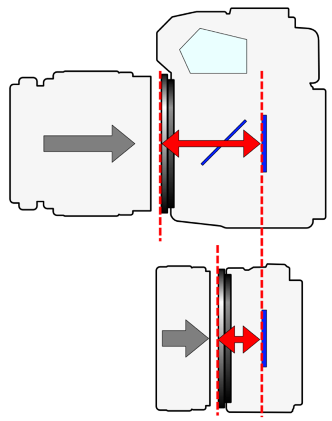
Figure 6 -– The focal flange distance, shown with red arrow, for a DSLR camera (top) and mirrorless camera (bottom). Image credit: Wikipedia/User Shigeru23
Learn more about focal flange distance and see the values for many camera designs and brands at this link.
Of course, once a camera is mounted to a flattener, corrector, or focal reducer, it must be inserted or threaded to the telescope’s focuser. That brings us to the concept of optical path length and how it factors in to a telescope’s available back focus discussed in Section 2. Let’s turn to that subject now.
4. Understanding Optical Path Length
With an understanding of the back focus of a telescope (Section 2) and the back focus of optical elements like field flatteners (Section 3), we now turn to the concept of optical path length. Almost everything, from filter wheels to cameras to off-axis guiders, has an optical length associated with it that needs to be accounted for, since it takes up part of the limited budget of a telescope’s overall back focus (see Figure 6).

Figure 7 – An illustration of several elements in the optical path behind a telescope’s focuser or a corrective optical element with a fixed and finite back focus. Your setup may only have some of these components, and they may be in a different order.
What is optical path length? For mechanical components like spacers, T-rings, thread changers and so forth, the optical path length is simply the physical length of the component, excluding any male threads or connectors.
For components that contain glass such as off-axis guiders, filters, diagonals, and so forth, the optical path length is more complex and cannot be determined simply by mechanical construction.
Here are a few examples of the optical path lengths of some common astrophotography components:
- Nikon/Canon DSLR plus T-ring: 55mm
- ZWO 8-position 1.25” filter wheel: 20mm + the small optical path length of the filter
- ZWO Filter Drawer for Canon Cameras: 26.5mm + the small optical path length of the filter
- Agena Deluxe Off-Axis Guider: 59mm
Adding a glass filter to the optical path also slightly changes the back focus distance. As a rule of thumb, when a filter is added to the optical path, the back focus increases by about 1/3 of the thickness of the filter. So a 1mm thick filter used behind a component with a 55mm back focus increases the back focus to 55.3mm. That’s only a significant change in the most demanding applications with fast telescopes.
Visual observers also need to consider the optical length of diagonals and especially binoviewers. For example, the Baader MaxBright II binoviewers have a straight-through path length of 110mm. When paired with a Baader T-2 Prism 32mm clear-aperture diagonal, for example, the optical length increases to 148mm. Both values are for the circumstance when no Baader glass-path corrector (GPC) is used. Adding this component has the effect of reducing the effective optical length.
Of course, knowing the optical path length of your accessories and how it relates to the back focus of your telescope is only useful if you know the available back focus of your telescope. As mentioned earlier, most manufacturers do not publish this specification. In many cases, unless you’re using many components for astrophotography with a telescope that doesn’t require a field flattener or focal reducer, or trying to use binoviewers, is not necessary to know the back focus of your telescope to any precision. If you want to use a DSLR or dedicated astronomy camera and a field flattener or focal reducer, it will likely work with most refractors and SCTs.
An exception: Newtonians. Many Newts have a very limited back focus and may not have sufficient inward focuser travel to even accommodate the additional 55mm optical path of a DSLR. However, some astronomy cameras tend to have a shorter path length and have a better chance of working with Newtonians. But using additional imaging accessories like filter wheels or off-axis guiders can still be challenging on Newtonians, even with non-DSLR cameras.
5. Additional Tips
A few more tips and suggestions when working with back focus and optical path length for astrophotography:
- For many imaging applications, it’s very useful to have M42 or M48 variable spacer rings in your toolkit to fine-tune spacing between camera and optical elements
- Rotators, used for camera orientation control, should typically be placed between the telescope focuser and the corrective optical accessory, but not between the optical accessory and the camera
- Flip mirrors are difficult to use after field flatteners and coma correctors because of their long optical path length
- Some corrective optical elements have threads for filters. However, to prevent vignetting, put filters as close as possible to the camera sensor
And here’s a useful online tool to help calculate back focus for a wide range of equipment.
https://cloudbreakoptics.com/blogs/news/calculating-back-focus-metal-back-distance
6. Examples
6.1 William Optics 50mm f/4 ‘RotoLock’ Guidescope
As mentioned in Section 2, many guidescopes have a limited back focus because they’re designed to work with only a small guide camera. The William Optics 50mm f/4 guidescope, for example, has a back focus of just 6.2mm. That means it will only accommodate small 1.25” ‘eyepiece-sized’ cameras like the ZWO ‘Mini’ cameras which have a sensor recessed just 6.5mm from the outer edge of the camera body. Another camera such as the ZWO ASI290MM with a 1.25” nosepiece will fit into this guidescope. But its sensor is recessed by 12.5mm from the back of the nosepiece, so it will not come to focus with this guide scope. It will come to focus with other guidescopes with a longer back focus such as the ZWO mini guidescope and the William Optics UniGuide-series of guidescopes.
6.2 Small Petzval Refractor, DSLR, and a NO Focal Reducer
Now let’s see how this all works for a small refractor, for this example, the Askar FR400 f/5.6 76mm Petzval refractor and a Canon DSLR. No field flattener is required for this telescope since it has its own corrective optics. With no flattener, we have access to the full 140mm back focus to insert accessories and cameras. The telescope includes an adapter for the focuser that terminates with a male M48x0.75 thread which, in turn, threads into the female thread M48x0.75 of a T-ring for a Canon DSLR. The T-ring and DSLR consume 55mm of back focus. So the focuser will have to be racked out to ensure the telescope projects a focused image onto the camera sensor. If the focuser has insufficient travel, an 6.3 Small Petzval Refractor, DSLR, and a Focal Reducer
Now, let’s consider what happens when adding the Askar 0.7x focal reducer designed for the Askar FRA400 telescope. This reducer brings the focal ratio down to f/3.9 and it has a working distance of 55mm. The reducer has female M68x1 threads that connect to the M68x1 threads on the telescope’s focuser (the M68-M48 adapter that’s included with the telescope must first be removed from the focuser). The camera side of the focal reducer has male M48x0.75 threads that attach to the female threads of a Canon T-ring that connects to the DSLR.
The back focus of the telescope is 140mm, but once the focal reducer is attached to the telescope’s focuser, this number is no longer relevant. We now have only to consider the 55mm working distance of the reducer. When the DSLR and T-ring are attached to the reducer, they take up all the working distance. The camera will come to focus, but there’s no space for any other components such as filter drawers or off-axis guiders.
While this example uses a particular telescope and focal reducer, it’s also applicable to other refractors with focal reducers or field flatteners with a 55mm specified back focus or working distance.
6.4 Small Refractor, Astronomy Camera, Focal Reducer, and Filter
Now let’s consider a small refractor with a field flattener with the standard 55mm back focus. And let’s use a ZWO ASI1600-series-Pro camera instead of a DSLR. This camera, with its 11mm T2-ring threaded to the camera body, has a sensor that’s recessed by 17.5mm, much less than the 55mm of a DSLR and T-ring. This provides a lot more space in the 55mm working distance of the Askar focal reducer (and any similar focal reducer used with other telescopes).
If we want to use an ASI1600MC-Pro one-shot color camera, we might need no other components in the path. In this case, to make sure the camera sensor lies 55mm from the focal reducer, we have to add an additional 37.5mm of path length. We do so by adding the 21mm and 16.5mm M42x0.75 rings that are supplied with this camera. With rings threaded to the camera and to the focal reducer, the camera will now operate at the correct working distance.
If we want to use a monochrome camera, say the ASI1600MM-Pro, then we might want to add a filter wheel to the optical path, for example, the ZWO 5-position 2” electronic filter wheel. ZWO designed this filter wheel to have a path length of 20mm, which along with the additional optical path length of 1mm from the filter itself, yields a total path length of 21mm. That makes it easy to swap out the 21mm ZWO spacer ring and insert this wheel and still meet the 55mm back focus requirement. This wheel includes an M54 (male) to M42 (female) adapter ring that adds to extra path length and make it easy to interface with the other threads in the optical path. Other ZWO accessories also have a 20mm path length that makes it easy to swap out the spacer ring and retain the correct back focus.
6.5 Schmidt-Cassegrain Telescopes and f/6.3 Focal Reducer
Celestron and Meade offer focal reducer/correctors for their f/10 Schmidt-Cassegrain telescopes that alter the effective focal ratio to f/6.3. These reducers thread on the back threads of the telescope tube and take the place of the visual back. For visual observation, simple thread the visual back onto the reducer, insert a diagonal and eyepiece, and you can use the telescope at f/6.3. The telescope has plenty of back focus to accommodate this accessory – simply turn the focuser to get a sharp visual image. As mentioned earlier, the focal ratio of the telescope may change slightly, but it’s too little to notice.
When the f/6.3 reducer/corrector is used for imaging, we need to work with its back focus - or what’s really its specified working distance (see Section 3.2). This distance is 105mm for Celestron’s reducer, much longer than reducer/flatteners for refractors. To use a DSLR and T-ring (which have an optical length of 55mm), it’s necessary to add a T-adapter tube with a path length of 50mm. The tube threads onto the reducer, then the T-ring of the camera threads onto the other end of the tube.
The Celestron or Meade f/6.3 reducer/correctors do not work with Celestron Edge HD optical tubes because they use a different optical configuration that incorporates correction for field flatness. These tubes have their own line of 0.7x focal reducers are made to match each EdgeHD aperture. These reducers preserve the original back focus of the telescope. The back focus for EdgeHD 9.25”, 11”, and 14” scopes is 146mm (5.75”). For EdgeHD 8” scopes, the back focus is 133.4mm (5.25”). To use these focal reducers directly with an EdgeHD telescope and DSLR and T-ring, an aperture-specific T-adapter is required.
6.6 Celestron RASA Telescopes
Celestron Rowe-Ackermann Schmidt Astrograph (RASA) scopes are built for astrophotography with built-in corrective optics with a back focus specification that must be considered when connecting a camera.
For the Celestron 8” RASA, the back focus specification is just 25mm. That means DSLR cameras will not work with this instrument, and there is virtually no room for many other optical accessories. Of course, since the camera is place up top in front of the corrector plate and blocks light from entering the telescope, it makes sense to keep optical elements to a minimum.
The larger-aperture 11” and 36cm Celestron RASA scopes have a larger back focus of 55mm, ideal for larger cameras and optical accessories.
7. Summary
The idea of back focus isn't particularly complicated. The confusion arises because amateur astronomers often mean different things when it comes to back focus. This article explained and showed examples of the main considerations when it comes to understanding the back focus of a telescope, a camera, and corrective optical elements such as focal reducers and field flatteners. This will help you select and use components for astrophotography and visual observing, and make sure you get the best image quality from your equipment.